What Is Clamping Tonnage?
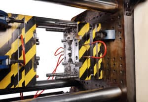 Injection molding is a unique manufacturing process that uses molten plastic and metal molds to create plastic parts for a variety of industries. The metal molds are made from two pieces of high strength steel. The molten plastic is forced into the metal mold under pressure. An equal or greater amount of pressure needs to be applied to the outside of the mold to keep the two pieces of the mold together and prevent the molten plastic from leaking out. The pressure being applied to keep the mold closed is called clamping tonnage or clamping force.
Why is Clamping Tonnage Important?
Clamping tonnage is an essential aspect in injection molding – it literally holds the process together. The injected material is pushed into the mold under pressure. There must be enough pressure to ensure the material reaches all parts of the mold evenly. Clamping tonnage is the opposing pressure needed to keep the mold closed while the stream of molten plastic is filling the mold. Not all injection molding machines will have the same clamping tonnage. A machine that does not have enough clamping tonnage will yield damaged parts.
The injection molding machine clamping force rating is typically stated in tons. A 200-ton machine is capable of producing a maximum clamping force equivalent to 200 tons of pressure. A clamping tonnage calculation formula is used to select a machine capable of exerting enough force to prevent part defects like excessive flash, burn, gloss level changes, and short shots. Too much pressure, however, might damage the mold or the machine.
The required clamping tonnage can be calculated from the cavity pressure inside the mold and the shot-projected area. The surface area of the part, the depth of the part, and, the material type (low-flow versus high-flow plastic) are all variables that will affect the clamping tonnage calculation formula.
Clamping Tonnage Calculation Formula
The required clamping tonnage can be calculated from the cavity pressure inside the mold and the shot projected area. Surface area of the part, the material type (low-flow versus high-flow plastic), and the depth of the part are variables that affect the clamping tonnage calculation formula.
Clamp Tonnage Rule of Thumb – Surface Area
The surface area of the part is the first variable used to determine the appropriate clamping tonnage. The surface area is calculated by multiplying the length of the part by the width of the part. For multi-cavity molds, multiply the surface area of one part by the number of cavities. Cored-out surface area is then subtracted from the overall surface area. The area of a cold runner should be taken into consideration if included in the mold.
Knowledge Base Subjects
- Advanced Technology Injection Molding
- Injection Molding Basics
- Calculate Cooling System In Injection Molding
- Calculate Plastic Mold Shrinkage
- Clamp Tonnage Injection Molding
- Custom Injection Molding Thermoplastic
- Gas Assist Injection Molding
- Instant Quote
- What is Mold Manufacturing?
- What are Examples of Injection Molding Products?
- What is 3D Molding?
- What is a 3D Printed Injection Mold?
- What is ABS Injection Molding?
- What is an Injection Molding Press?
- What is Ceramic Injection Molding?
- Liquid Silicone Molding 101
- Micro Molding 101
- What is HDPE Molding?
- What is Mold Tooling?
- What is Polymer Molding?
- Precision Injection Molding Basics
- What is Prototype Plastic Molding?
- What is PVC Injection Molding?

The surface area calculation is then multiplied by a clamping tonnage factor. Depending on the material, typical tonnage factors can range from two- to eight-tons per square inch. For example, a 6 in. x 6 in. part has a surface area of 36 square inches. The material being used will determine the clamping tonnage factor. The material used for this example part calls for a mold clamping tonnage factor of five. Doing the math yields 36 * 5 = 180. Based on the calculations, the injection mold machine will need to be capable of exerting at least 180 tons of clamping tonnage.
A 10% safety factor should be added, bringing the needed clamping tonnage to 198 tons. At this point in the calculations, a 200-ton machine would be a good choice. It is important to select the right machine with the proper clamping tonnage. Too much clamping tonnage can damage the parts, mold, and machine.
Clamp Tonnage Rule of Thumb – Melt Flow
After calculating the surface area, the next variable to consider is how the chosen material will flow. Plastic resins are rated according to viscosity or thickness. The flow rating is expressed as a Melt Flow Rating (MFR), or Melt Flow Index (MFI), which can be found on the material data sheet.
There is an inverse relationship between viscosity and the MFR. Materials with a low viscosity (thin) have a high melt flow and require less clamping tonnage. Materials with a high viscosity (thick) have a low melt flow and require more clamping tonnage. Thicker materials will almost always require a higher clamping tonnage
Clamp Tonnage Rule of Thumb – Part Depth
A part with a depth of one inch or more will require further clamping tonnage calculations. This does not refer to the thickness of the part wall, but to the total depth of the part from top to bottom or back to front depending on the mold orientation. For every inch of depth over one inch, an extra 10% needs to be added to the clamping tonnage calculation formula.
In this example we will use a part that is four inches long and four inches wide, yielding 16 square inches. The material multiplier is five. 16 * 5 = 80 tons of clamping force. The part is also two inches deep, which adds an additional 10% for every inch over the first inch (80 * .10 = 8). An additional eight tons of clamping force are added bringing the total to 88 tons. Another 10% is added for safety (88 * .10 = 8.8). Bringing the new total to 96.8 tons. According to the clamping tonnage calculation formula, a machine capable of exerting 100 tons of clamping force should be used to make the part.
After completing the clamping tonnage calculation formula, it is now time to choose the right machine with the appropriate amount of clamping force. As previously mentioned, there is a risk in choosing an injection-molding machine with too much clamping tonnage as it can cause damage to the parts, mold, and machine.
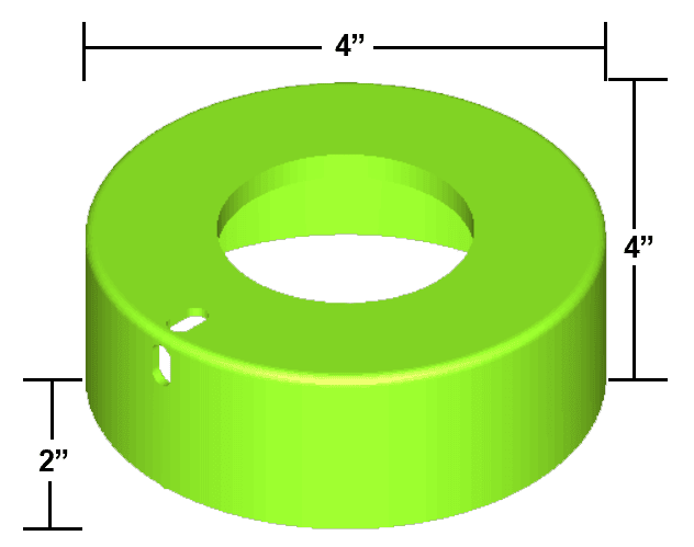
This piece is 4 inches long and 4 inches wide, which gives us 16 square inches. The multiplier we are using for our material is 5, so we will multiply 16 by 5 and get 80 tons. Since our part is 2 inches deep, we have to add 10% for every inch over the first one. So, we need to add an additional 8 tons for a total of 88 tons. For safety, we add 10%, and our new total is 96.8 tons. Therefore, we need a machine with a minimum clamp force of 100 tons to mold our part.
Potential Harm From Excess Clamping Tonnage
Burned parts, gloss level changes, and short shots are some of the typical molding defects caused by excessive clamping tonnage. Too much clamping tonnage can also have negative long-term effects on the mold. Excess clamping tonnage can cause rolled parting lines, crushed vents, as well as break inserts and crack the core or the cavity block.
Too much clamping tonnage can also damage the injection mold machine by cracking the hydraulic cylinder mounting plates. It can also cause deformed platens or even fracture the machine frame.
Selecting an injection-molding machine with too much clamping tonnage will also affect the bottom line. Injection mold machines with higher clamping tonnage generally cost more to run than machines with a lower clamping tonnage. Besides the risk of ruined parts, cracked molds, and damaged machine, a machine with too much clamping tonnage will be more expensive to operate. Selecting a machine with too much clamping tonnage for the part can cause the total cost of the job to be unnecessarily higher, resulting from damaged parts, molds, or machines as well as downtime and the costs of repairing the damage.
Injection Molding Tonnage Calculator
The clamping tonnage calculation formula presented above is an easy way to estimate the required clamping force for each project. The experts at ICOMold by Fathom are experienced in calculating the required clamping tonnage for every injection-molding job and will work to save the customer time and money on every project. ICOMold does not offer an injection molding tonnage calculator since the clamping tonnage calculation formula is simple to follow and should be considered only as a rough estimate. Contact the experts and ICOMold by Fathom today and get started on your next injection-molding project.